Troubleshoot a Truck Antenna Installation
Before I dive in, I was motivated to write this by a buddy of mine from the state of Washington, thanks Rick. We were bullshitting about CBs and he stated how he hates that when he asks others “in the know” a radio question, he is then treated like he is not part of “secret CB society”. I nearly fell off my chair (not from a bad hip, gimme a break). I though I coined the phrase years ago dealing with the radio shitheads of old. Back then I would ask the “local gurus” for information on how they came up with their decisions, and all I got back was “this is how it’s done”, or they shot an arrogant look my way and was told “you wouldn’t understand”. WTF, you ain’t talking to me like that and now I’m gonna beat you at your own game! It was kept a mystery because when it came down to it, they didn’t know and made it some kind of a religion completely ignoring solid radio engineering techniques. This caused me to dive into antenna theory, relearn calculus (puke), and design antennas BEFORE any of the software that’s now available all over the place. Damn, I did it the hard way. What I present here is a practical approach of real world antenna engineering techniques to make an antenna perform as it should on your truck.
T & A
[that stands for trucks and antennas, stay focused!]
$%#K! You replaced everything and you have 3:1 SWR on every channel. Time to troubleshoot methodically. Tools needed: patience and something to test continuity. A DMM usually has a continuity checker or most auto parts have a lighted one for those who are tone deaf, or, just use the Ω setting. Zero is continuous, ∞ is not. This is the one I use →
If you have an antenna that has a coil, check from the shaft of the bottom part of the coil to the top or the mast portion. I know you are familiar with “brand new bad in the box parts”, and sorry to say, sometimes you will find that the brand new coil is broken internally. Check it to make sure it’s good and has continuity. Here, Short good (continuous), open bad.
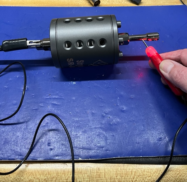
Continuous = short, light on. Not continuous = open, no light.
1. Disconnect the coax from the radio and the stud.
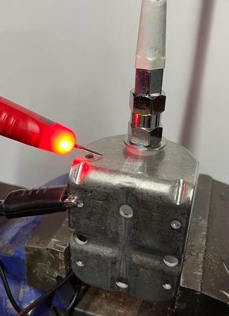
2. Now check for continuity from the metal portion on the bottom of the antenna to the bracket. Should NOT have continuity here!
Here, SHORT bad, OPEN good.
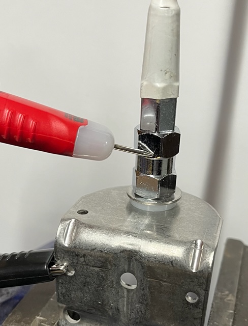
3. If it’s shorted, remove the antenna and stud, check when reinserting the stud that the nylon washer goes on top and there is a small ring on the nylon that must seat in the bracket hole perfectly.
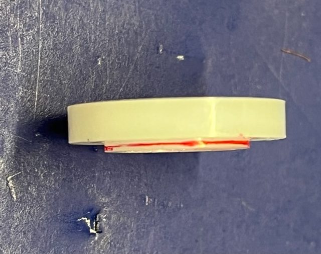
I highlighted it in red for folks who insist that those 1.5x from the grocery store make you see just fine.
You need the 2.5X, but just get it into the hole.
The threaded part of the stud MUST be electrically isolated from the rest of the truck, OPEN. Or in other words any part of the antenna screwed into the stud must be electrically isolated from the rest of the truck, OPEN. If not, fix it.
4. GROUND
This may be the single most issue with T & A! Old, new, it does not matter. If the base of the antenna mounting bracket is not continuous to the frame of the truck, you only have half of an antenna. SWR will be sky high and if you let this go your radio will shit the bed. Fact.
Now I am going to use western style mirror brackets as an example. If you have a question about another style, call me, there are more than a couple of issues out there. Watch out for the new tri axles where the antennas screw into a hole in the back of the mirror housing. Take that pretty chrome plastic mirror cover off and you will find the mounting stud screwed into the PLASTIC mirror frame. Yeah, good luck with that. Call me.
Let’s say you have a pre 06 379. Now don’t break my balls because I’m not talking about the truck you drive, it’s just an example. Most 379 mirror brackets are mounted to the door. Important: the door must be closed to check the SWR! Now if she has a few light years on the odo, chances are the door hinges are as wobbly as your knee and the door catch is as worn as your L3 and L5S1 spinal joint. Statically, maybe if you shut the door just right, you have a good ground. Drive, and that shit is all over the place, SWR speaking. Solution, a VERY SHORT grounding strap from the door to the door frame. You should replace the door bushings and catch, but I have a better chance at hitting Power Ball. Go cautiously with a grounding wire! I had a driver whose old man wrapped a piece of wire around the mirror bracket then connected it to the air filter. She asked “does that work?” My wise-ass NY attitude said, “yeah as well as your marriage and it’s as ugly as your old man”. He laughed and instead of loosing a customer, she ripped it down and had me fix it. By adding a long length of wire, that antenna was tuned (resonant) for the military bands far away from channel 19.
Painted Mounting Brackets.
Don’t sacrifice performance for good looks, (Rick!). I get it. I know it has to look cool. Hell, that’s why so many truck chrome shops out live CB shops! But fundamental antenna practices have to be met. If not, it’s like taking your diabetic medication instead of your viagra. Blood sugar up, the rest down. If the antenna mounting bracket off the back of the cab or sleeper is painted or you went the extra mile and had it powder coated, sand the shit out of the bottom to bare metal. Not the whole thing, just around the hole for the stud. You want the bottom of the stud to have electrical continuity to the bracket which is electrically continuous to the frame. Check it. If not, call me.
5. Check the coax. Put the coax back on the stud and go into the cab, door shut Everything is connected except the radio. Put one lead of your meter/light on the center pin and the other on the screw portion of the PL 259. S/B NO CONTINUITY, (open). If it is not, the coax shit the bed and is shorted out internally. By process of elimination, you proved the antenna is good, stud is good, you have a good ground so that’s all that is left.
6. Mashing the coax. Let’s assume your radio has a built in SWR meter. It’s not the greatest but will get you close. Without putting the radio in its mount, check the SWR. If it’s okay, mount her up.
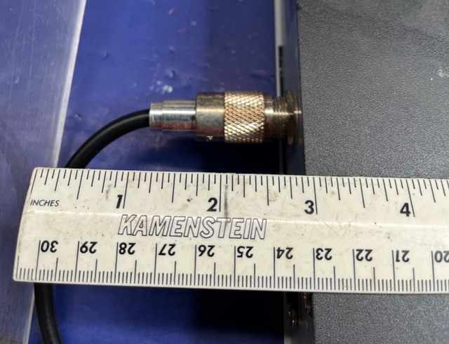
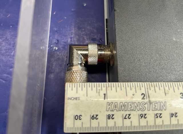
Now check the SWR. If it goes up, the end of the coax is getting mashed meaning it’s breaking connection most likely from too much of an angle on the plug end. A 90 degree PL 259 could take the stress off that connection.
Hope this helps. Any questions, shoot them my way.
This article is the sole property of NBSR and cannot be redistributed or reproduced without expressed permission from NBSR.